A core induction test is a test technique performed to find hot spots in/at the stator cores of rotating machines and engines. The reason for a hot spot is local damage of the lamination. This type of testing has been widely used for many years and we have performed testing for several customers.
When performing maintenance of rotating machines and engines, a check of the electrical integrity of the laminated stator iron may be necessary. These inspections are usually performed due to suspected hot spots which can be caused by several mechanical damages of the lamination, ground fault currents due to winding failure, abrasion of lamination insulation due to lamination vibration or due to improper cleaning agents or other reasons.
It is widely known that lamination short circuits cause short circuit currents when the stator core is activated, i.e., when the iron flux is forced back. During operation these short damages occur, and the hot spots are created. If the temperature in a hot spot exceeds the maximum permissible value of the lamination insulation, the insulation is damaged which will lead to a continuous and rapid increase of core fault.
How the test is performed
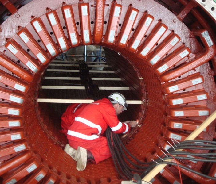
A temporary exciter winding is placed around the stator core during the test (single-core rubber cable), this temporary exciter winding is energized, forcing a back iron flux. The back iron flux must be chosen as close as possible to that back iron flux which is used during normal machine operation because the temperatures of lamination hot spots depend on the back iron flux.
Voltage and current are monitored in the temporary magnetization circuit. This provides information about the iron loss during the core test. During the core test, only the iron in the stator core is under voltage, but during operation of the machine, the magnetic flux penetrates parts of the rear iron as well as the core teeth and parts of the rotor.
The core damages are heated by the corresponding short-circuit currents Ik, more specifically by the I2R losses in the hot spot. Theoretical evaluations and tests have shown that these I2R losses are in the order of a few hundred watts. Comparing these with the core test iron losses, it becomes obvious that it is completely impossible to conclude from a loss measurement about the presence or absence of core damage and hot spot.
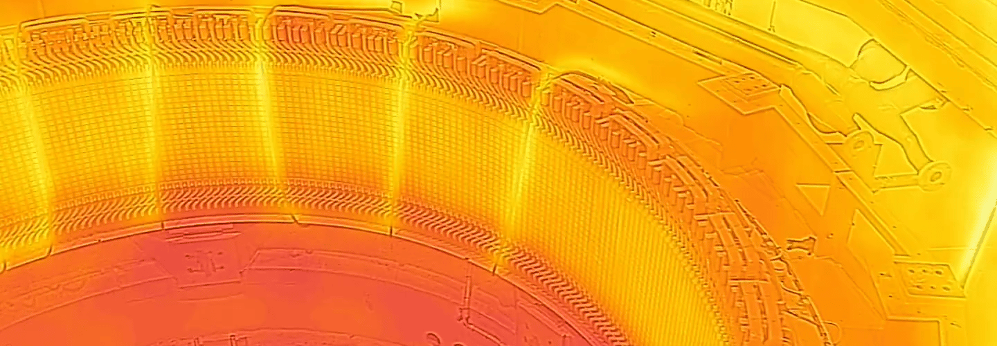
The actual detection of hot spots is usually done by scanning the boring surface by hand and verifying the actual temperature with an electronic thermometer. The use of infrared cameras to detect and document hot spots should only be used for special problems. (Our clients primarily use IR cameras and touch during testing).
General requirements
An adjustable power supply (such as a generator or a battery) is required to activate the temporary magnetization winding. When we perform such tests, we carry all the necessary equipment to perform the test, including the power supply. The actual voltages and currents depend on the core in question and the power requirements must be calculated before the test or recorded from previous tests. Typical power supply requirements are 200-400 Volts and 100-500 Amps. The power source of the temporary magnetizing winding must be suitable for continuous operation with a phase load, the insulation must be heat resistant and double insulated.
Setting up the instruments and meter reading requires at least one skilled engineer, and it is recommended that another engineer takes care of the continuous power supply.
Although it is common to touch the bore surface to detect hot spots, it can be dangerous to do this when the stator is energized. This requires safety measures.
Contact us for more information on how we perform testing, or if you need other solutions.
Back to overview